Connecting inputs, decisions and visible outputs on an Arduino Uno.
Five Microcontrollers 1 exercises using Arduino C++, breadboard circuits, serial debugging and a Tinkercad simulation. These are guided course assignments using supplied briefs and starter code, not original product designs or custom PCB work.
The submitted materials include completed code, state diagrams, photographs and demonstration video files. This page presents selected photographs, a serial-output screenshot and code-review observations. The videos have not been independently reviewed, and no new hardware tests were run for this portfolio.
01 / SENSOR INTERFACING
Ultrasonic proximity indicator
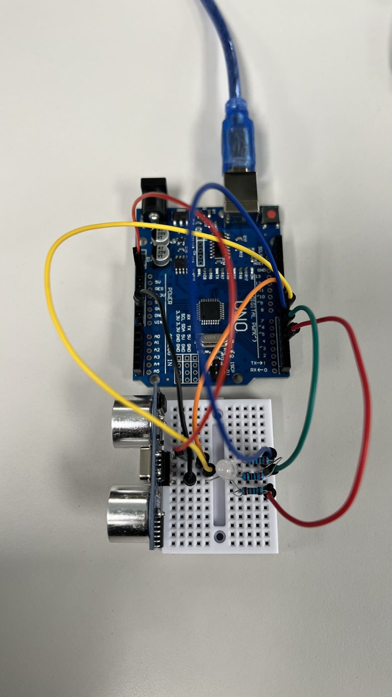
Connected an HC-SR04 sensor and RGB LED to an Arduino Uno. The submitted sketch measures echo duration, converts it to centimetres and selects red, yellow or green output using 10 cm and 30 cm thresholds.
Submitted photograph of the breadboard prototype. A photograph documents assembly, not measurement accuracy or correct operation across all three zones.
Boundary: No reference-distance comparison, error distribution or repeatability data is available. The submitted logic treats no echo as green, so it does not distinguish a distant target from an invalid reading. This is a classroom indicator, not a safety system.
02 / ANALOG INPUT + PWM
Joystick-controlled RGB lighting
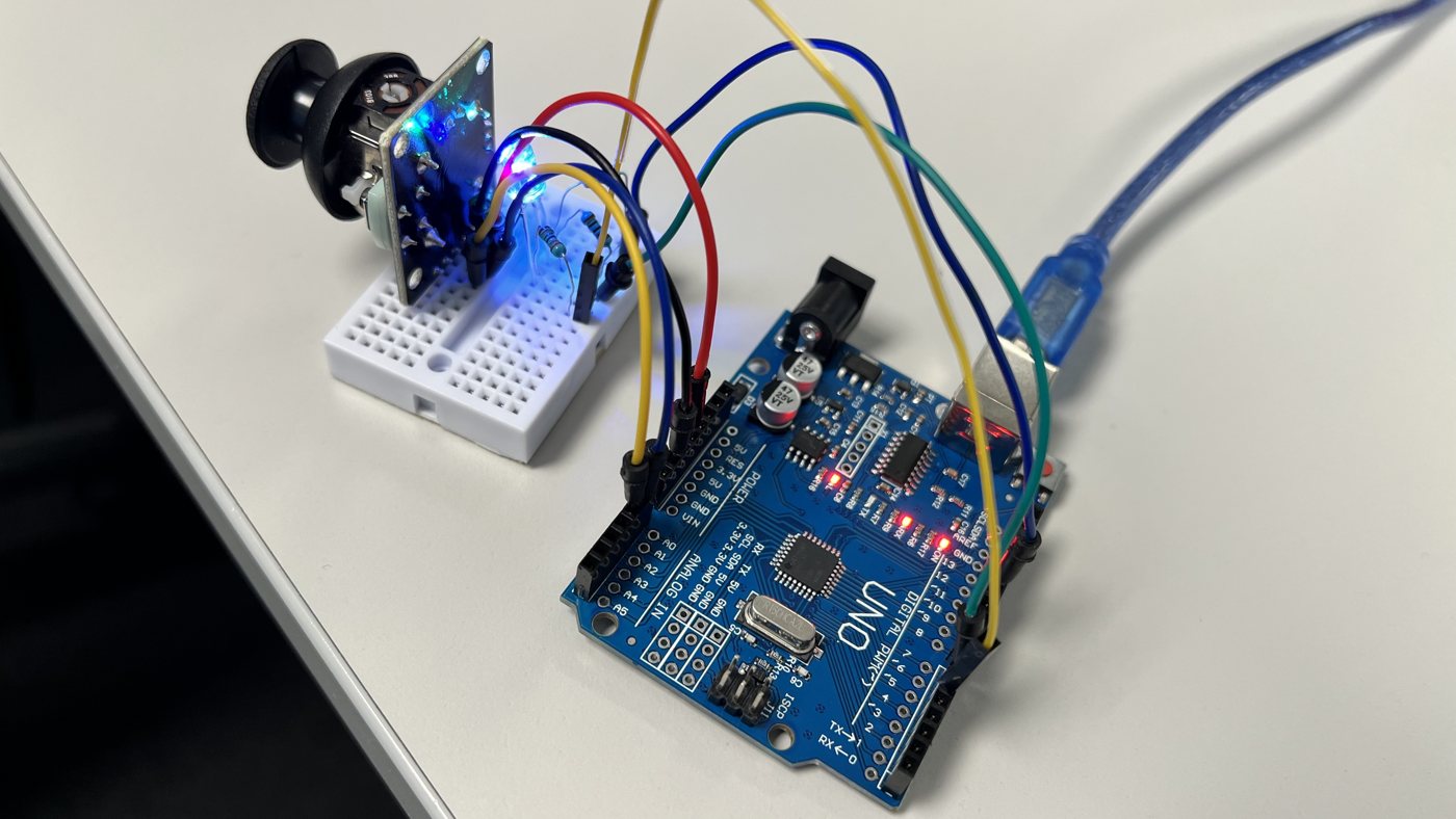
Completed analog input and PWM output logic: the joystick’s X axis controls red and green together; its Y axis controls blue. Each 0–1023 input is mapped to a 0–255 output, with raw and mapped values printed over serial.
Submitted photograph showing the powered joystick/RGB assembly. Dynamic response and PWM timing are not established by this still image.
Implementation observation: Direct mapping puts a centred axis near half output; it does not create a centre-off dead zone. No linearity or response-time measurements are claimed.
03 / MODULAR C++ + SERIAL DEBUGGING
Serial calculator
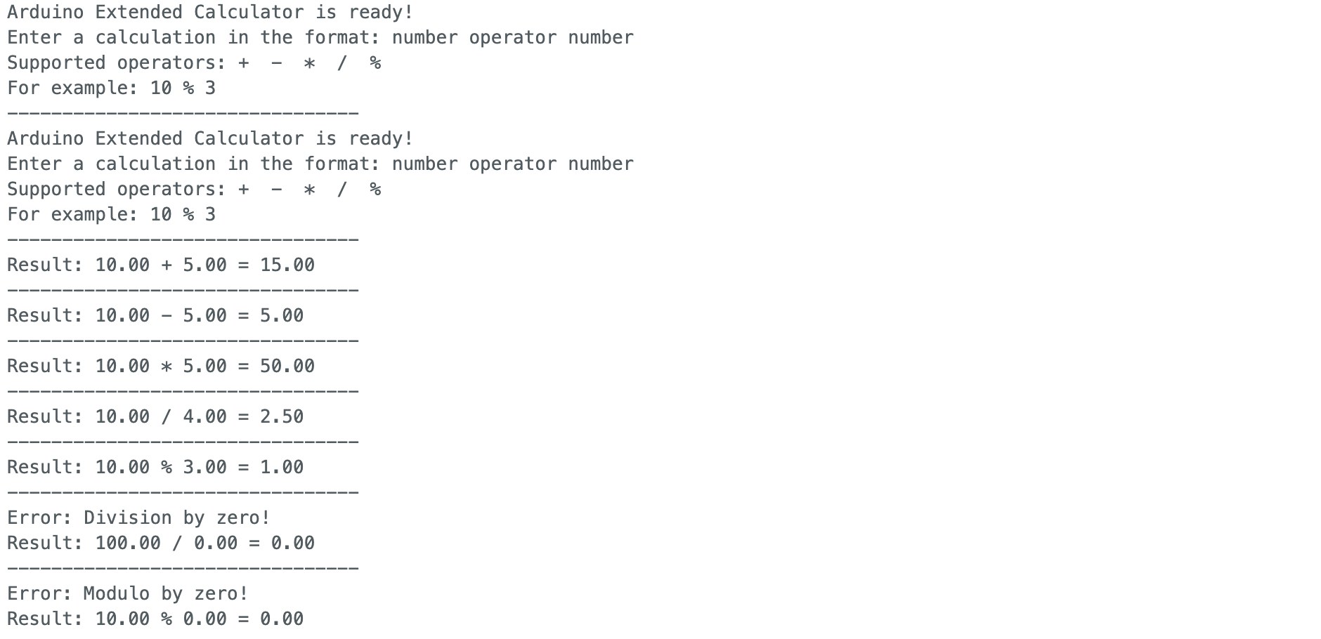
Completed arithmetic functions and dispatch across an Arduino sketch, a header and an implementation file. The submitted code includes floating-point remainder and explicit checks for division and modulo by zero.
Submitted Arduino IDE screenshot: 10 + 5 = 15; 10 − 5 = 5; 10 × 5 = 50; 10 ÷ 4 = 2.5; 10 modulo 3 = 1. Division and modulo by zero display error messages. Open full-size serial results.
Boundary: This screenshot is a record of selected examples, not an exhaustive test suite. Error paths also print a numeric zero result; the interface does not separate an invalid calculation from a valid zero using a structured status.
04 / STATE MACHINES
Two ways to control LED state
Push-button blink controller
A Tinkercad exercise with OFF, slow-blink and fast-blink states. The completed code adds falling-edge detection, a 50 ms lockout and non-blocking timing with millis(). The supplied diagram and code document the intended transitions.
Boundary: Simulation coursework. Physical switch-bounce resilience and blink timing have not been measured.
Serial RGB controller
The submitted sketch accepts y, p and t commands and selects mixed RGB outputs through a state-based switch. A state diagram and demonstration video file accompany the submission.
Boundary: Code structure was reviewed; the video’s command-to-colour behaviour has not been independently verified.
What the evidence supports
Completed coursework implementations, documented breadboard assemblies and selected serial calculator results. These materials support a discussion of practical learning in sensor interfaces, control flow, PWM and debugging. They do not establish custom PCB design, calibrated sensing, production readiness or full system acceptance.